Accuracy Check of the Measuring Tool
The largest influence is exerted by the ambient temperature. In particular, temperature differences that occur from the ground upwards can refract the laser beam.
For this reason, place the measuring tool as close as possible to the work surface and secure it with the base running as near parallel to the work surface as possible.
In addition to external influences, device-specific influences (e.g. falls or heavy impacts) can also lead to deviations. For this reason, check the angle accuracy each time before beginning work.
Should the measuring tool exceed the maximum deviation during one of the tests, please have it repaired by a Bosch after-sales service.
For this check, you will need a clear area of firm, level ground measuring approx. 10 × 5 m.
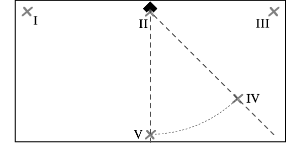
- Place the measuring tool in one corner of the measuring area. Switch the measuring tool on and set it up so that the 0° laser line runs down the long side of the measuring area and the 90° laser line runs down the short side of the measuring area.
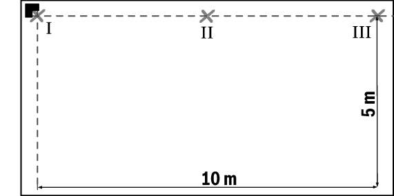
- Mark the point where the two laser lines intersect on the ground (point Ⅰ). Make another mark in the centre of the 0° laser line at a distance of 5 m (point Ⅱ) and at a distance of 10 m (point Ⅲ).
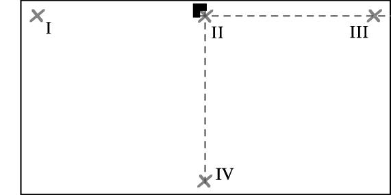
- Position the measuring tool (without rotating it) at a distance of 5 m so that the intersection point of the laser lines meets point Ⅱ and the 0° laser line runs through point Ⅲ. Mark the centre of the 90° laser line at a distance of 5 m (point Ⅳ).
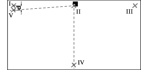
- Rotate the measuring tool through 90° so that the centre of the 0° laser line runs through point Ⅳ. The laser lines must still intersect at point Ⅱ. At a distance of 5 m, mark the centre of the 90° laser line as point Ⅴ as close as possible to point Ⅰ.
- The discrepancy d between points Ⅴ and Ⅰ is the actual deviation of the 0° and 90° laser lines from the right angle.
The maximum permitted deviation over the measuring distance of 2 × 5 m = 10 m is as follows:
10 m × ±0.2 mm/m = ±2 mm. The discrepancy d between points Ⅰ and Ⅴ must therefore amount to no more than 2 mm.
For this check, you will need a clear area of firm, level ground measuring approx. 10 × 5 m.
- Place the measuring tool in one corner of the measuring area. Switch the measuring tool on and set it up so that the 0° laser line runs down the long side of the measuring area and the 90° laser line runs down the short side of the measuring area.
- Mark the point where the two laser lines intersect on the ground (point Ⅰ). Make another mark in the centre of the 0° laser line at a distance of 5 m (point Ⅱ) and at a distance of 10 m (point Ⅲ).
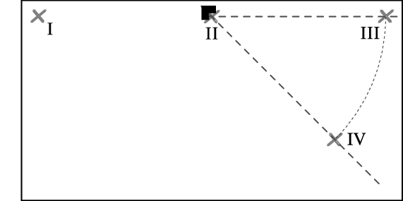
- Position the measuring tool (without rotating it) at a distance of 5 m so that the intersection point of the laser lines meets point Ⅱ and the 0° laser line runs through point Ⅲ. Mark the centre of the 45° laser line at a distance of 5 m (point Ⅳ).
- Rotate the measuring tool through 45° so that the centre of the 0° laser line runs through point Ⅳ. The laser lines must still intersect at point Ⅱ. At a distance of 5 m, mark the centre of the 45° laser line as point Ⅴ.
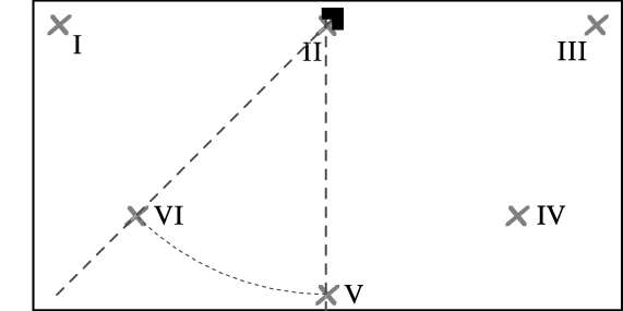
- Rotate the measuring tool through 45° so that the centre of the 0° laser line runs through point Ⅴ. The laser lines must still intersect at point Ⅱ. At a distance of 5 m, mark the centre of the 45° laser line as point Ⅵ.
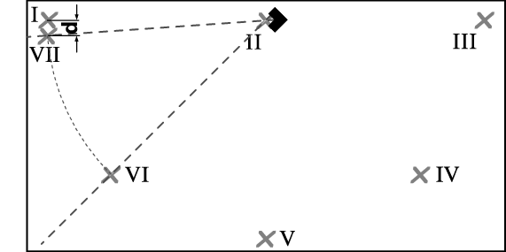
- Rotate the measuring tool through 45° so that the centre of the 0° laser line runs through point Ⅵ. The laser lines must still intersect at point Ⅱ. At a distance of 5 m, mark the centre of the 45° laser line as point Ⅶ as close as possible to point Ⅰ.
- The discrepancy d between points Ⅰ and Ⅶ is the actual deviation of the 0° and 45° laser lines.
The maximum permitted deviation over the measuring distance of 4 × 5 m = 20 m is as follows:
20 m × ±0.4 mm/m* = ±8 mm. The discrepancy d between points Ⅰ and Ⅶ must therefore amount to no more than 8 mm.
* The value of ±0.4 mm/m is based on the angle accuracy of ±0.2 mm/m plus a potential uncertainty of 0.2 mm/m when rotating the measuring tool.